A belt is easy to reduce to the characters printed along its outer face. The installed drive contains more information: curved pulley edges, the position of a hub, a straight belt span, and neighboring hardware. In these EexcavaStart field records, three independent examples show how those details contribute different parts of the mechanical picture.
An outer face beside a pulley groove
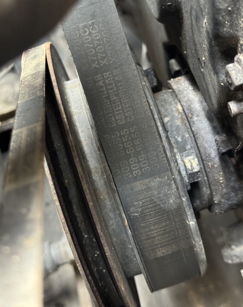
The first close-up places a broad black belt face next to a dark, recessed pulley groove. A metal hub is partly visible on the other side. The belt carries repeated printing and fine surface lines, while the nearby metal edge curves away from the camera. These are distinct features, even though they occupy one small area.
This distinction matters when describing an installed drive. The belt’s visible outer face is not the same feature as the groove beside it. A close view of both preserves their relative position, rather than making the printed strip stand in for the whole arrangement. The image shows only a local section, with some surfaces hidden behind the belt and neighboring structure.
A span between two visible pulley areas
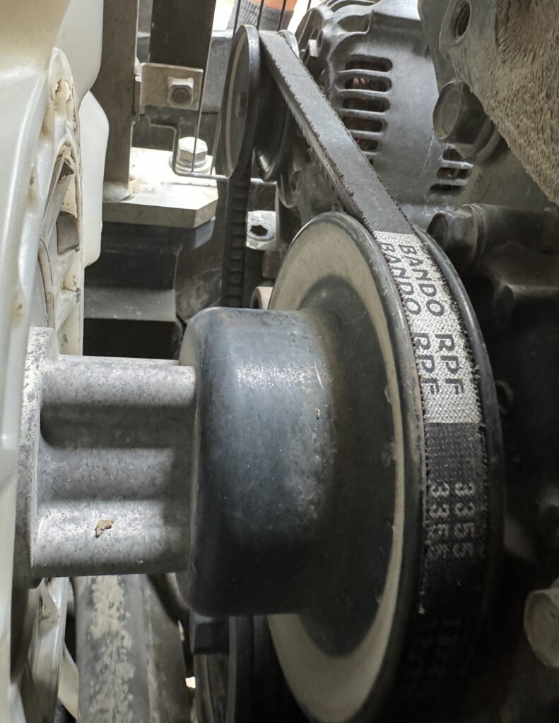
In the second example, the belt curves around a large foreground pulley and runs diagonally toward a smaller pulley in front of a vented alternator housing. A pale fan blade sits to the left; metal brackets and fasteners occupy the space behind the belt. The straight span and the curved region around the foreground wheel are both visible.
Here, the useful information is the relationship between parts. The belt, fan, alternator housing and fixed structure share a confined opening. Removing that context from the description would lose the position of the belt relative to its surroundings. The view remains partial: it shows one visible span, not a complete routing diagram.
Two hand-held lengths, seen from the outer face
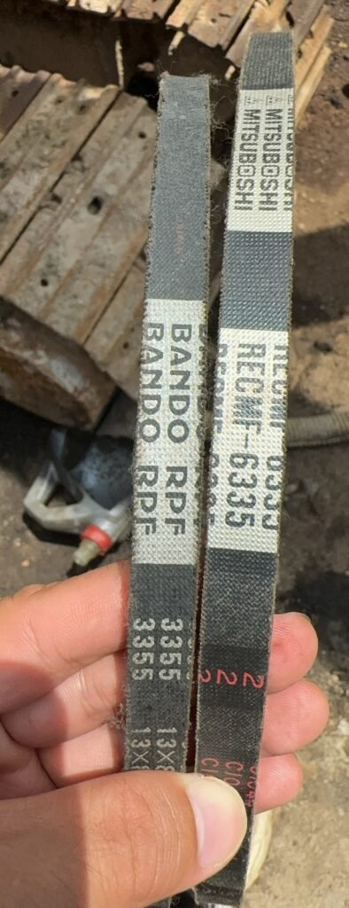
The third example changes the subject from installed layout to surface detail. Two belt lengths are held beside one another, with textured dark faces, light printed panels and visible fibers along portions of their edges. Their printed panels differ, and the fingers provide support rather than a measuring reference. Neither a complete loop nor a measured cross-section is presented.
These are separate observations, not a replacement sequence or a matched set. Printing is retained as part of the real surface, not adopted as a verified specification, authenticity statement or interchange reference. The records do not establish belt dimensions, tension, pulley alignment, remaining service life, machine fitment or a repair result. Their value is more specific: they keep the belt face, pulley geometry and installed surroundings from being mistaken for the same kind of information.
Questions and answers
What does the installed view add beyond the printing on a belt?
It shows local relationships: the visible pulley rim, belt span, hub and nearby structure. In the wider example, the fan blade and vented alternator housing help locate the visible span. The complete belt route is outside the view.
Can similar printed characters confirm that two belts interchange?
No. The hand-held example preserves the actual printed surfaces, but it does not establish measured length, width, cross-section or an approved application. The two displayed lengths are not presented as a replacement pair or matched set.
Do surface lines or visible edge fibers prove that a belt has failed?
No. Those details can be described as visible appearance. These records provide no functional test, wear limit, service history or diagnosis from which to assign failure or remaining life.
Can these images be used to set belt tension or judge pulley alignment?
No. There is no calibrated tension measurement, verified alignment reference or complete procedure here. The article is a field-detail record, not an installation, adjustment or tensioning guide.
Related reading: Engine and Component Records: Configuration Before Conclusions. Browse News & Insights.