A machine cover is more than its painted outer face. A broad curve, a returned edge and a small mounting tab describe different parts of its structure. The yellow cover in these field details has all three, together with a mesh section and visible areas of missing paint. A separate loose cam lock adds another set of features: a threaded body, retaining hardware and an offset metal arm.
The long edge and the mounting tab
Viewed along its length, the cover has a rounded shoulder above a narrower inner edge. The contour changes direction rather than staying parallel to the nearby straight furniture edge. A tape lies along the inner side, while part of the mesh remains visible below it.

Near the end of the cover, a narrow metal tab rises beyond the main yellow surface. Its elongated slot is a local mounting feature, distinct from the broad curve. The tab’s position and bend are therefore different information from the overall outline of the cover. Neither can be replaced by simply describing the item as a yellow panel.
The cross-profile is not the material thickness
The closer detail shows a tape extending from a fixed edge, crossing the cover’s rounded shoulder and bending down its front. The change from a straight span to contact with the curve is visible. So are the raised return and the mesh section below the painted surface.

This is a view of the cover’s local cross-profile, not an exposed cut through the material. The depth of the rounded form and the thickness of the skin are different quantities. A number read at a bend in the tape would also need a clearly defined start and end reference before it could be treated as a dimension. No numerical measurement is taken from this record.
The hardware behind a latch
The loose cam lock shows a silver threaded body above a black handle. A hexagonal nut and toothed washer sit around the body. At the opposite end, a metal cam extends sideways and bends away from a flat line near its tip.
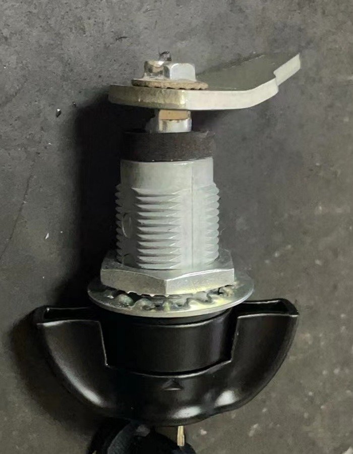
These features separate the mounting region from the part that reaches behind a panel. The barrel, retaining nut and cam offset are not one interchangeable measurement. The side view makes their physical relationship clear, while leaving the actual panel cutout and mating catch outside the record.
The loose lock is an independent example, not a confirmed accessory for the pictured cover. Color, outline and visible hardware establish no machine model or compatibility. The original paint loss and surface marks remain unchanged; they do not by themselves establish damage severity, a required repair or a successful outcome. The useful record is the visible structure: the cover’s contour and local mounting feature, alongside a separate example of latch hardware.
Cover and cam-lock questions
1. Does the tape across the curved cover show its material thickness?
No. It crosses the rounded form and bends over the surface. That records a local profile rather than an exposed material section. No numerical dimension is established here; a measurement needs a defined reference and the correct measuring method.
2. What does the slotted tab add to the cover record?
It shows a local mounting feature that sits beyond the main painted surface. Its slot, position and bend are different information from the cover’s overall curve. They do not identify a machine model or establish a matching bracket.
3. Is the loose cam lock supplied with the pictured yellow cover?
No such relationship has been confirmed. It is a separate hardware example showing a threaded body, retaining nut, washer, handle and offset cam. The corresponding panel cutout, catch and compatibility are not established.
Related reading: Cab and Control Parts: Position, Housing and Connection Records. Browse News & Insights.